What's new
05/31/2026:A new version of the SV705 device has been released. Website design updated.
09/27/2025:Added support for Deye 3phase inverters
07-08-2025:Added support for Jsdsolar inverters
07/26/2025:Connecting SV701 via WiFi + additional features. See useful links
06/30/2025:Added an alternative mode of operation via a wattmeter, updated the site design
06/29/2025:Added support for Deye 1phase inverters
13-06-2025:Added support for Growatt SPF5000, SPF6000 inverters
02-06-2025:Added support for LuxPower SNA 3000-6000 inverters
05/18/2025:Wiring diagrams for SV701 and WiFi datalogger for simultaneous operation have been published
12-05-2025:Added support for two PV inputs for PowMr 10.2kW inverters
05/03/2025:Confirmed support for DATOU BOSS 6200w inverters. They work on the Voltronics&Clones protocol. Attention, these inverters have a non-standard connector layout!
04/15/2025:The site design has been completely updated.
03/30/2025:Added support for Anenji 11kW inverters.
03/26/2025:Added support for MUST inverters.
02/28/2025:Official opening of the site. Supports 4 types of inverters.
Ways to utilize excess solar energy
Green energy is inexorably entering our daily lives. Many households have already acquired small solar power plants, the basis of which is a hybrid solar inverter.
However, owners of such stations often face the problem of excess solar generation, when the panels can generate more energy than is currently consumed. We offer an effective solution to this problem using the SV701,SV705 devices.
1. Using on-grid inverters
On-grid inverters allow you to discharge excess energy into an external electrical network. This is a technically good option, but it comes with a number of difficulties:
- The high cost of such inverters compared to off-grid models;
- Bureaucratic difficulties associated with registration of generation into the network;
- Problems with certification. Many budget inverters do not have the necessary certificates for generating into the network;
- The need to purchase additional equipment (bidirectional electricity meters and generation quality control devices);
- Low tariffs for reverse generation in some countries;
- Lack of access to the external network in remote regions, during natural disasters or military operations.
2. Payload for excess energy
A more affordable solution is to use an additional payload to recycle excess solar energy. Energy-intensive devices such as electric water heaters or space heaters are already present in many homes. However, they have a fixed consumption, and the excess energy from solar panels is variable, depending on the time of day, weather and battery charge level.
More expensive inverters usually have the ability to dump excess solar energy into an additional port using a functionSmartLoador similar. But budget inverters do not have this function. It is for such inverters that our device was originally created in 2025SV701, which provides control of additional load and utilization of excess energy directly. Later we received requests from owners of inverters that have a standard functionSmartLoad. It turned out that this function is not suitable for everyone, since it works through charging and discharging the battery, and the additional inverter port may be occupied by other equipment. Now we have added support for such inverters. Taking into account operating experienceSV701in 2026 we released the next improved version of the device SV705.
Devices SV701, SV705 control a special type of solid-state relay (optotriac) with LA (4-20mA) or VD (0-10V) characteristics and can operate in two modes. The first mode is a regular dimmer with manual remote control of the output power. The second mode is “smart regulation” of power, which allows you to select only excess power from solar panels.
Theoretical foundations
Let's see how it works. Any solar hybrid inverter includes a control unit for the maximum power point of solar panels (MPPT), which allows you to extract maximum power from them at the current illumination. Exists several algorithms searching for this point and it is not known in advance which algorithm a particular inverter uses. What they have in common is that they all determine the point of maximum power on the current-voltage characteristic of the solar panel, always in a fairly narrow voltage range, which is approximately in the zone of 0.7-0.8 relative to the no-load voltage of the solar system. Also, all inverters behave identically in the case when the power of solar energy from the panels begins to exceed the power of all its consumers. In this case, they “step out” from the maximum power point to reduce the generation power by increasing the voltage at the solar input. Observe the performance of your solar inverter when it has enough load to utilize all the solar energy. You will see that the solar input voltage at this moment is always within a certain narrow range. Now watch it when the inverter load is not enough to absorb all the solar energy. You will see that the voltage has moved out of that narrow range and increased.
This is illustrated graphically in the figure below. There are typical dependences of current on voltage and power on voltage for a solar cell. These graphs show where the inverter moves the power take-off point in case of excess solar energy.
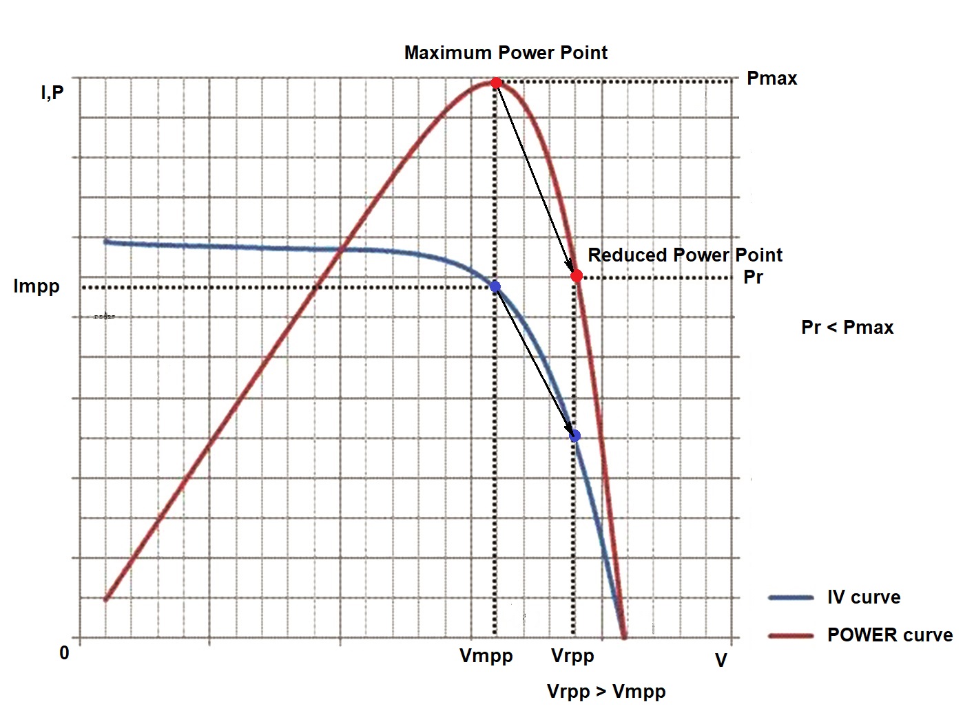
It is this pattern that our devices use to controllably increase or decrease the inverter load in order to return the system to the maximum power zone. SV701, SV705 organize a second circuit, external to the inverter, to search for the maximum power point! The device polls the inverter once per second and quickly regulates the load.
The boiler is also a battery :)
I would like to dwell separately on such an energy consumer as an electric boiler. Many solar inverter owners view it as an annoying and power-hungry load on their system. If you connect the boiler directly to the inverter, this is indeed the case. But using a boiler in conjunction with the SV705 allows you to look at it from a different perspective. Hot water is always needed for domestic use. To heat 100 liters of water by 50 degrees (from 20C to 70C) you really need to spend quite a lot of electricity - about 5.8 kWh. But a boiler can also be considered as an energy storage device! With good thermal insulation, it retains thermal energy for a long time. Moreover, the cost of such a 5.8 kWh storage device will be an order of magnitude lower than the cost of a comparable electric battery. Therefore, it is quite reasonable to dump “excess” electrical energy there and then use hot water as needed. Moreover, SV701, SV705 allow you to do this in “smart mode” without overloading the inverter.
Another alternative load for SV701, SV705 may be other types of heaters. For example, an auxiliary heater for heating a house in cold seasons or a pool heater in warm seasons.
Compatibility issue
SV701, SV705 devices are theoretically compatible with any hybrid inverters, regardless of their power and output voltage (120V or 230V). The main requirement is to support the data exchange protocol via the RS-232 port or via the RS-485 port. Possible connection options for various types of inverters are shown here SV701 circuits, SV705 circuits. Operating experience of SV701, SV705 devices has shown that many Chinese budget inverters of different brands have the same exchange protocols. However, it is possible that representatives of the same brand may have different protocols. Our devices currently support 13 different protocols.
| Protocol | Brand/Models | Interface |
|---|---|---|
| Voltronic & Clones 1PV | Voltronic, PowMr, Anern, Daxtromn, Edecoa, Dataoboss, Axioma, etc. | RS232 |
| Voltronic & Clones 2PV | Voltronic and clones with two PV inputs | RS232 |
| PowMr 10.2kW 2PV | PowMr 10.2kW, Anern 10.2kW, etc. | RS232 |
| PowMr Modbus 1PV | PowMr, Anern, Daxtromn, Edecoa, Dataoboss, etc. | RS232 |
| Anenji 4/6kW 1PV | Anenji, Aninerel, EASUN SMG II, ISOLAR SMG II, POW-HVM-5.5H-48V | RS232 |
| Anenji 11kW 2PV | Anenji 11kW, Easun 11kW | RS232 |
| JSD Solar 1PV | Jsdsolar J4000, J5500 | RS232 |
| Must 1PV | Must series PH1800, PH1900 | RS485 |
| SRNE 1PV | SRNE | RS485 |
| Deye 1ph 2PV | All single phase Deye | RS485 |
| Deye 3ph 2PV | All Three Phase Deye | RS485 |
| Lux Power 2PV | Lux Power SNA3000-6000 | RS485 |
| Growatt 2PV | Growatt SPF5000,SPF6000 | RS485 |
We plan to regularly expand the list of supported protocols.
Useful links
Disclaimer
We warrant that our equipment will perform as described on this website when properly installed and used.
However, responsibility for correct assembly, connection and use rests entirely with the user. We are not responsible for equipment damage, system malfunction, loss of data, or other damage caused by failure to comply with instructions, use of the device in unsuitable conditions, or tampering with the design.
Use of our kits is at your own risk. Before you begin, make sure you understand all aspects of the system assembly and subsequent operation. In case of doubt or lack of experience, we recommend seeking professional help.