Alternative mode with wattmeter
In the process of adding support for new types of inverters, we encountered the fact that it is not always possible to establish an information connection with inverters. Some inverters do not have appropriate external interfaces or have an encrypted protocol (for example PowMr 4.5/6.5kW). We have also received inquiries from grid-tie inverter owners who would like to dump excess solar energy from their systems into ballast loads rather than limit generation using limiters. To support such devices, we have developed an alternative operating modeSV701. In this mode, instead of connecting the device to the inverterSV701connects to a wattmeter.
Theoretical foundations
This method uses AC flow monitoring to determine the presence of excess solar energy. An external AC network is used as a reference. Grid-tie inverters or hybrid inverters work like this in the so-called mixing mode. When there is enough solar energy, they power the entire load from the sun. When there is a lot of solar energy, they reduce their generation so that there is no export to the external network. When solar energy is insufficient, external grid energy begins to mix into the load. Therefore, the adjustment algorithm looks like this. A bidirectional wattmeter is installed at the input of the external network. The load at the inverter output increases until there is no longer enough solar energy and small consumption from the external network begins. This small fixed energy import is then maintained at a constant level by adjusting the ballast load consumption. Moreover, it does not have to be an import. If desired, it is also possible to fix the export of energy to an external network at a certain level.
Practical implementation
There are many wattmeters/energy meters on the market that claim to be bi-directional. We tested several models and found that many of them were not suitable for our purposes in one way or another. We have selected two inexpensive suitable models - these areTAC1100иCM7646. They have approximately the same metrological characteristics. The first model has its own screen and structure for installation on a DIN rail. The second is available in two modifications - with an internal shunt for currents up to 20A and with a current transformer for currents up to 100A. Typical connection diagrams in different versions are shown below. Any of these wattmeters can be used with a grid-tie inverter or hybrid inverter in mix mode or in grid generation mode.
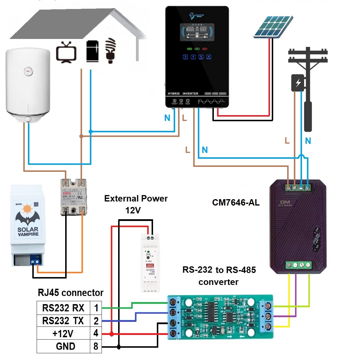
Typical circuit with wattmeter CM7646-AL
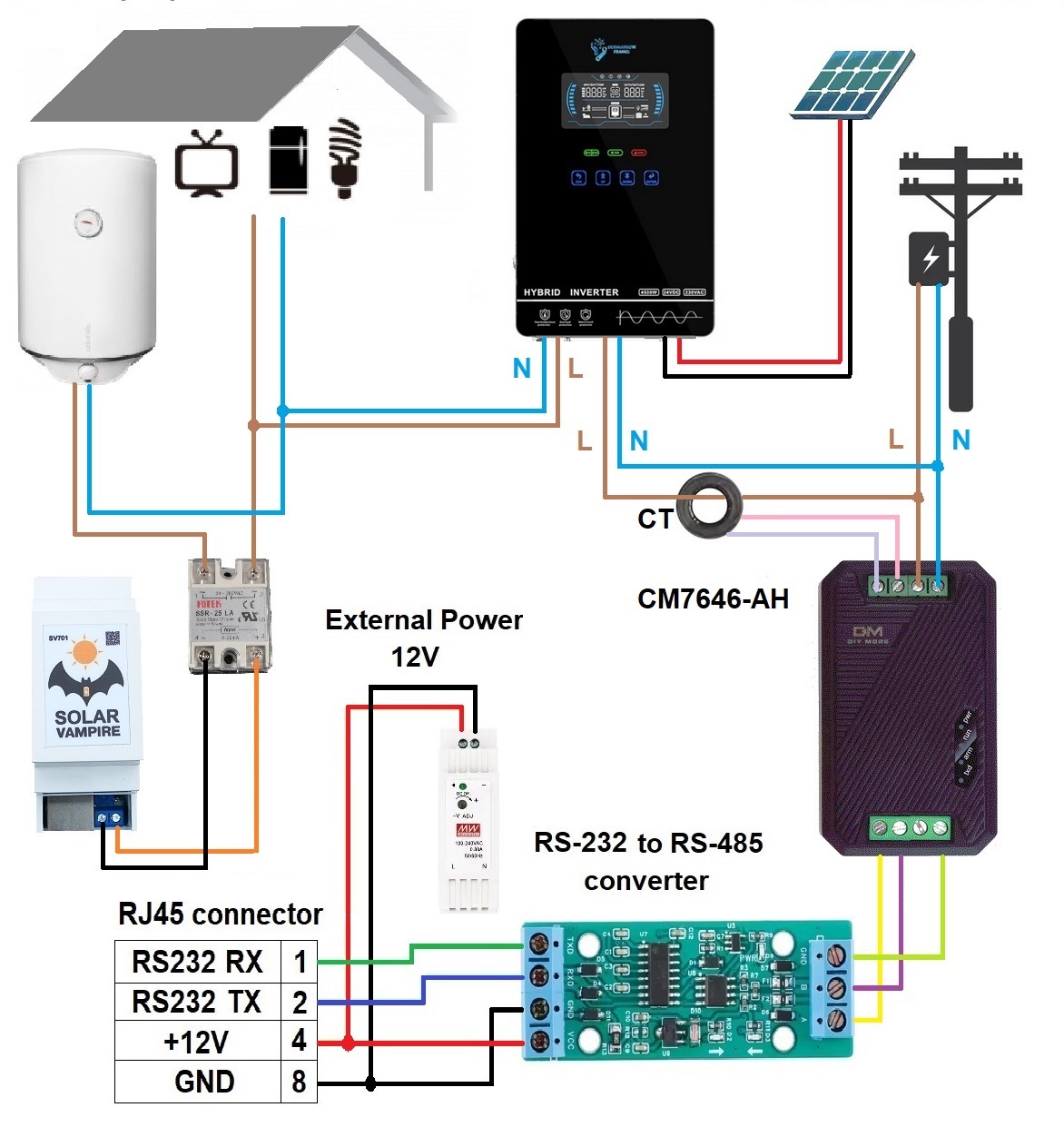
Typical circuit with wattmeter CM7646-AH
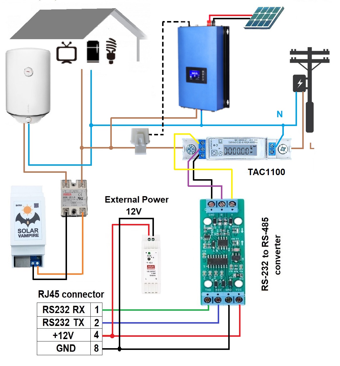
Typical circuit with TAC1100 wattmeter
Control via Android application
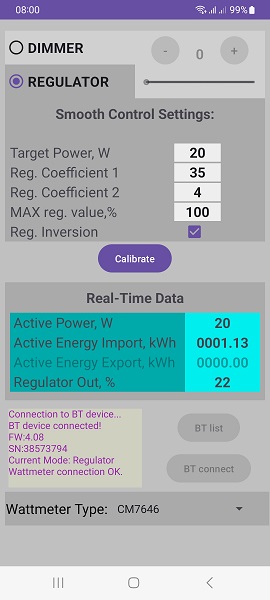
The control in this application is similar to the control in the inverter communication application. Bluetooth pairing is performed in the same way. You can read about this in the main section. Now the target value is set to the power at the output of the wattmeter. A positive value means import of electricity, negative - export. Coefficient K1 sets the overall speed of adjustment, coefficient K2 - the speed of reaction to large power surges. There is also a MAX Reg Value output power limiter. The next adjustment is Reg.Inversion, it sets how the regulator should react when the target value increases - reduce or increase the power of the ballast load. For the given typical schemes, inversion must be turned on. The Calibrate button is necessary to adjust the system to a specific heater and a specific SSR relay. Calibration is required, but it only needs to be done once. The calibration process itself lasts about a minute. At this time, the device runs the load twice from 0 to 100%. During calibration, it is advisable to disconnect all other loads in the circuit except the ballast loadSV701. Or at least ensure a constant level of consumption of the remaining loads during calibration. The Real-Time Data section displays data received from the Wattmeter. This is current power as well as energy. The TAC1100 wattmeter calculates energy export and import separately. The CM7646 power meter sums the energy from both directions, so it all ends up in the import section.
As mentioned above, in a circuit with a wattmeter, the presence of excess energy is determined by its flow. The target value must be set to the power level from the network and the system will try to maintain it using feedback. For most applications, it is reasonable to set it to 20-50W. When solar energy production from the inverter decreasesSV701will reduce the ballast load, and if it increases, it will increase it. The selection of coefficients is carried out as follows - if K1 is small, then the adjustment will occur slowly, if it is too large, then the system can be over-adjusted to the point of self-excitation. Similarly with the K2 coefficient. The default settings are fine for most systems.
Features of the mode
Power adjustment in such a system does not occur instantly due to the inertia of wattmeters. Therefore, with sudden changes in consumption or generation, the system needs a few seconds to return to a stationary point. At these moments, small short-term energy flows in both directions are possible. For example, a hybrid inverter, even in mixing mode, can provide generation to the network at such moments. Don't let this surprise you, this is a feature of the admixture mode. Such flows are always possible in the mixing mode and without the participation of SV701. Simply a bidirectional wattmeter allows you to see these flows.
Tests with a grid-tie inverter SUN1000 G2 showed that the wattmeter gets along quite well with the standard limiter of this inverter. The system can increase ballast power using a wattmeter, but further reduces generation during attempts to generate into the network.
Disclaimer
We warrant that our equipment will perform as described on this website when properly installed and used.
However, responsibility for correct assembly, connection and use rests entirely with the user. We are not responsible for equipment damage, system malfunction, loss of data, or other damage caused by failure to comply with instructions, use of the device in unsuitable conditions, or tampering with the design.
Use of our kits is at your own risk. Before you begin, make sure you understand all aspects of the system assembly and subsequent operation. In case of doubt or lack of experience, we recommend seeking professional help.