Connection diagrams SV705
- Basic connection diagram
- Inverters with non-standard RS232 connection
- Dataouboss inverters— non-standard RJ45 pinout
- Inverters with DB9 connector
- Jsdsolar J4000, J5500
- Inverters with RS485 connection.
General information
For all schemes, it is necessary to make a cable and connect it to the RS485 port of the SV705 device. Also, all circuits require an external 12V power supply. Some of these inverters are connected via the BMS connector, which has two interfaces on one connector: RS485 and CAN. In this case, the RS485 pins must be used to communicate with the SV705 and the CAN pins to communicate with the battery.
- Simultaneous connection of SV705 and statistics reading devices.
General information
If your inverter is equipped with a single RS-232 or RS-485 port, then it may already be occupied by a Wi-Fi module or other data collection device. In general, these ports allow you to have only one master device (Master) during communication. In our case, such a Master is eitherSV705or wifi datalogger. We have developed three ways to combine the operation of these devices.
- Additional schemes.
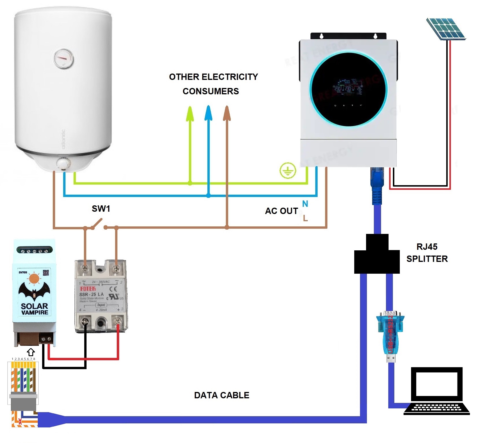
Basic connection diagram
Basic connection diagramSV705shown below. This circuit is suitable for many budget inverters Anern, Daxtromn, Edecoa, PowMr, Easun, Axioma, Anenji and many other brands withan RS232 port, which is connected to an RJ45 connector and has a standard wiring.. On the inverter, this port is intended for connecting wifi data loggers, computers and other devices.SV705has the same connector with the same pin arrangement, so to connect to the inverter you can use a regular patch cord for Internet connections.
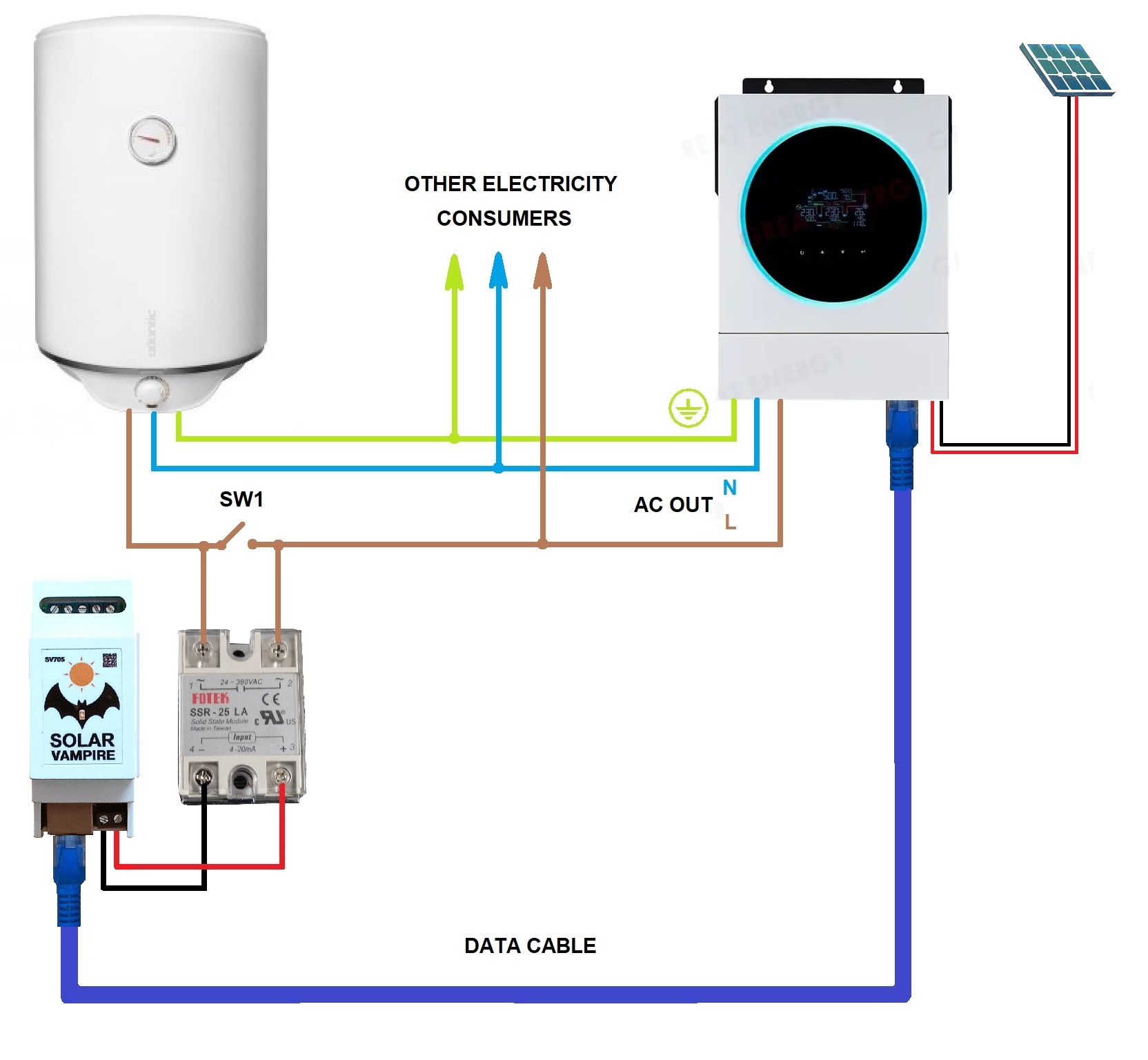
To control power, you need to use a solid state relay (SSR) with an LA characteristic (current regulation 4-20mA). You can also use a relay with a VD characteristic (voltage adjustment 0-10V). If the load power exceeds 1.5-2 kW, then the solid-state relay must be installed on a heat sink. Links to trusted sellers of such relays and other necessary components and parts are locatedon this page.
Using switch SW1 you can connect the boiler to the network directly. This way it can be used in its usual mode. This may be necessary, for example, on a cloudy day.
Connection diagrams for other inverters
For all single-phase inverters, the power section is connected in the same way as in the basic diagram. The differences will be in the connection of information exchange, as well as in the connection of additional power sources. First, let's look at inverters that have an RS232 port with a different RJ45 pinout. Below is a diagram for Datouboss inverters. To connect them, you need to make your own cable according to the diagram.
Connection diagram of SV705 to Datouboss inverters

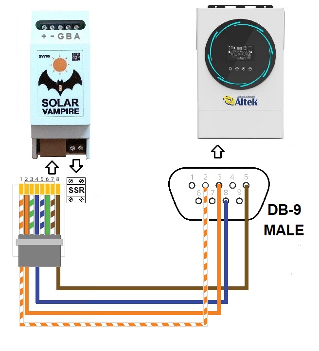
Connection diagram for inverters with DB-9 connector
Some inverters Voltronic, Axioma, Altek and others have an RS232 port connected to this connector. It is necessary to make a cable according to the diagram.
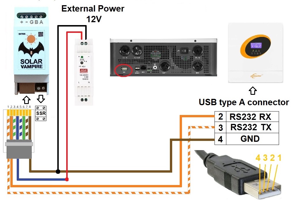
Connection diagram of SV705 to Jsdsolar J4000, J5500 inverters
These inverters have an RS232 port connected to a USB Type A connector. It is necessary to make a cable according to the diagram. To power the SV705 you need to connect an external 12V power supply.
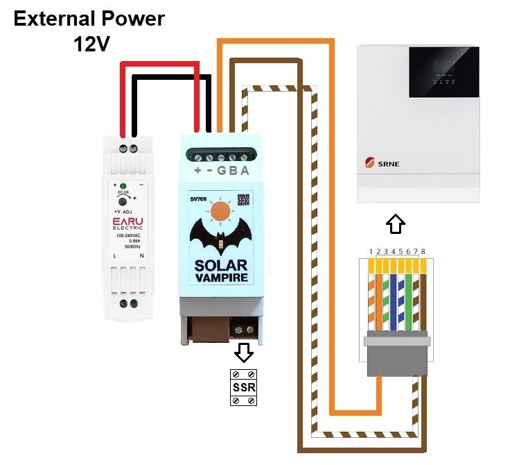
Connection diagram of SV705 to SRNE inverters
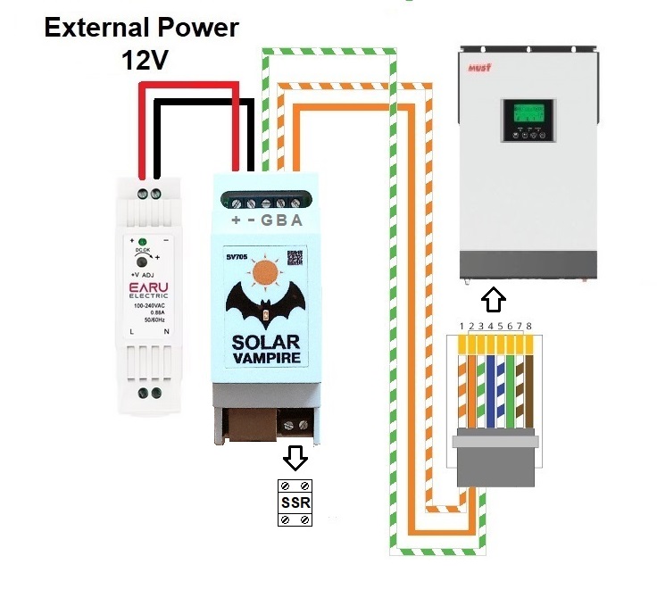
Connection diagram for SV705 to MUST inverters
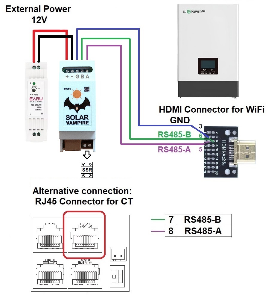
Connection diagram of SV705 to LuxPower inverters
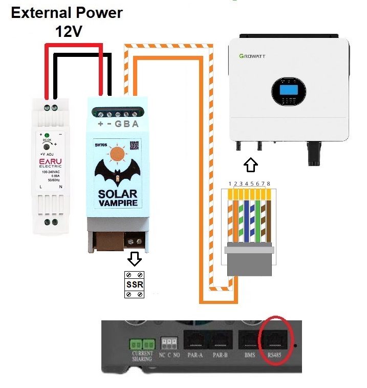
Connection diagram of SV705 to Growatt SPF inverters
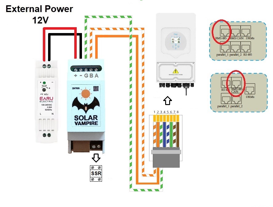
Connection diagram for SV705 to Deye 1phase inverters
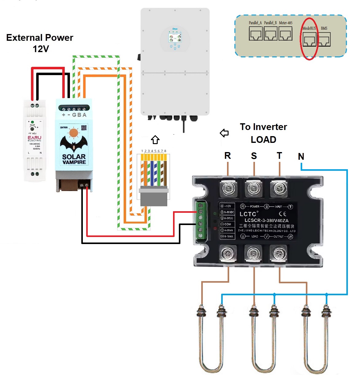
Connection diagram for SV705 to Deye 3phase inverters
These inverters are connected via RS-485 via the ModeBUS connector. To control the load you will needthree-phase relay version.Also for such a relay you will needradiator
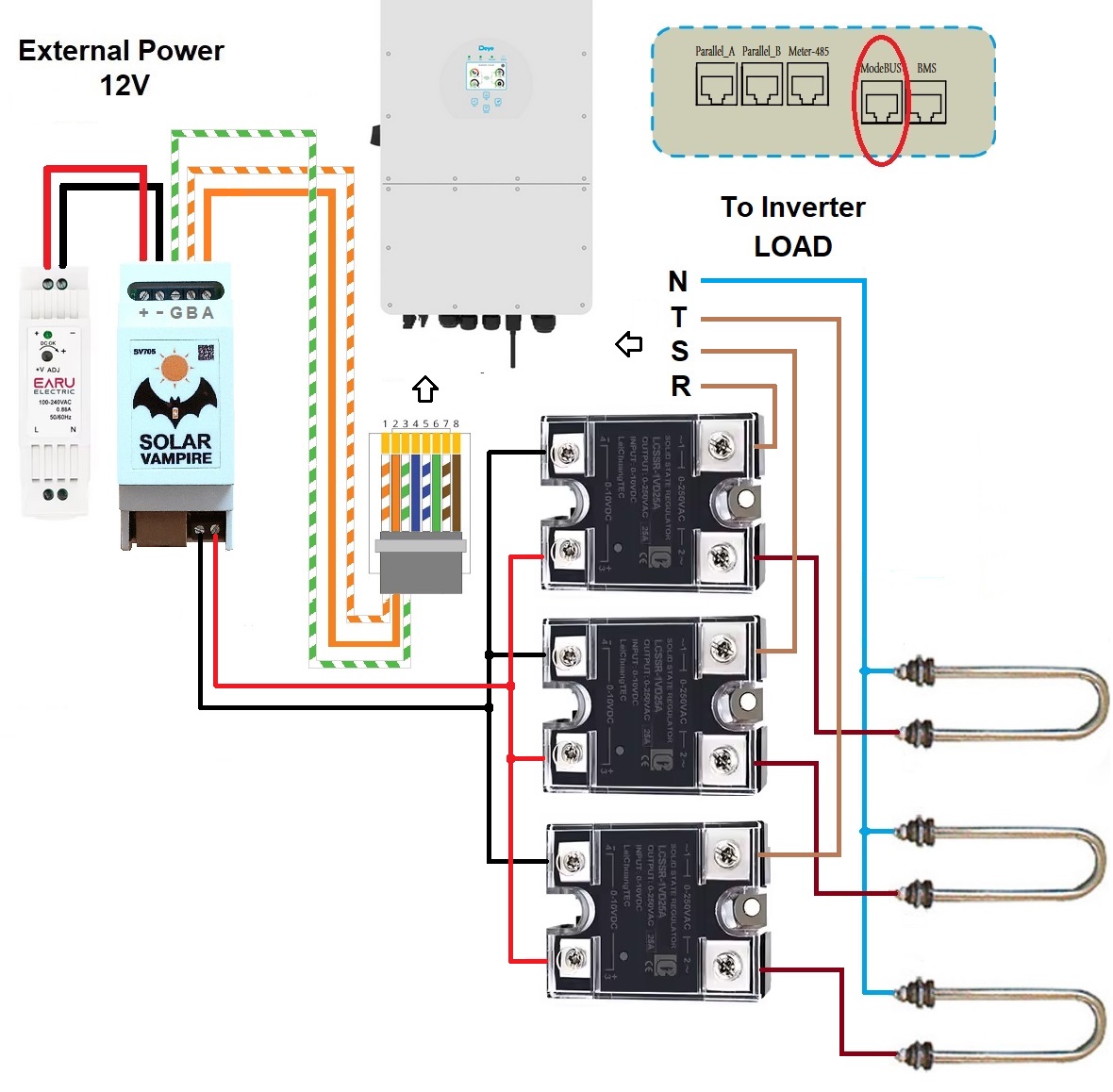
Alternative diagram for connecting SV705 to Deye 3phase inverters
Here are usedsingle-phase SSR relays with VD control characteristic (0-10V).
Parallel connection of SV705 and statistics collection devices
The first method is to use a laptop or tablet running the program to collect statistics instead of cloud servicesMultiSIBcontrol. This program only works with inverters that have the Voltronic&Clones protocol. Such a program collects much better statistics compared to cloud services. After all, it collects data once every 2 seconds, while cloud services poll the inverter once every 5 minutes. Thanks to frequent polling, the work of such a program can be combined with workSV705. To do this, you need to connect both devices to the inverter via an RJ45 splitter (all identical contacts are paralleled) or independently solder such a cable to connect two devices at the same time. Changed connection diagramSV705shown below.
On the cable that directly connects to the SV705, you need to cut the orange conductor (pin2). This will block our device from sending requests.
Requests will now be sent by a computer or tablet.SV705will “eavesdrop” on the inverter’s responses, extract the necessary information from them and regulate energy consumption.
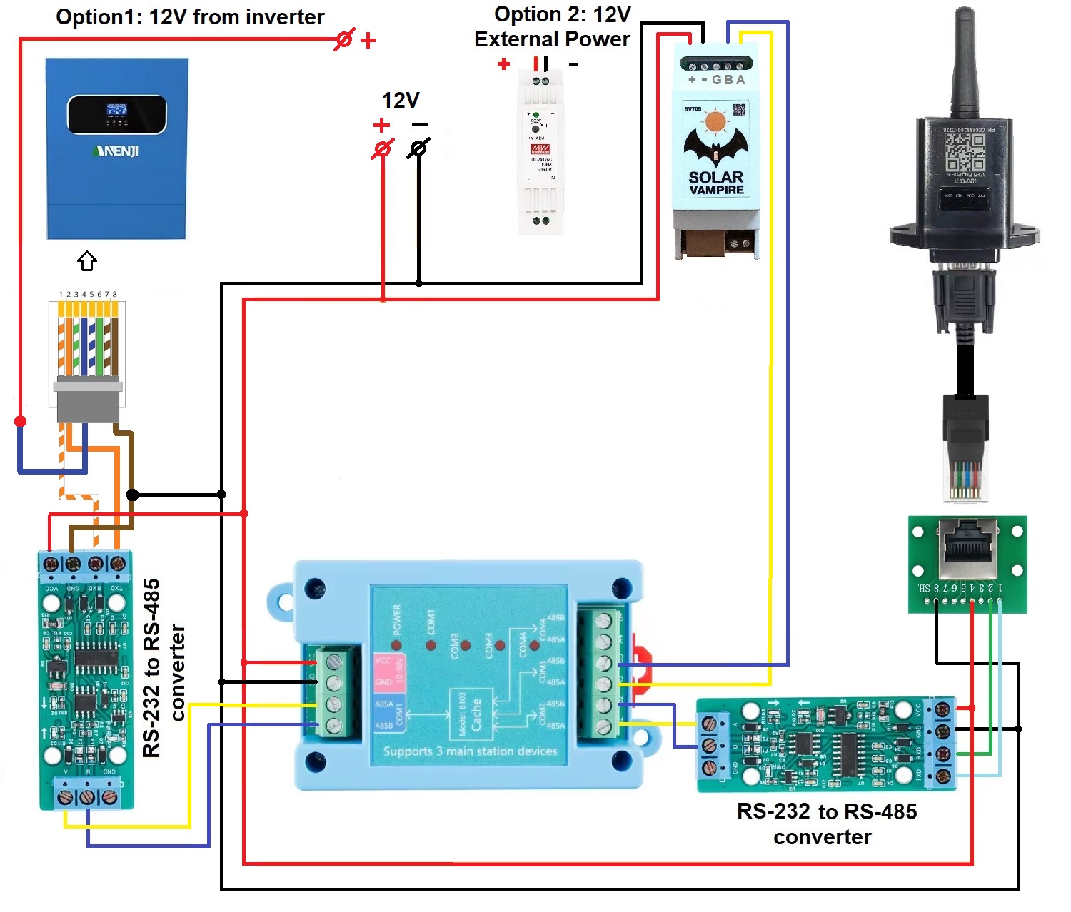
The second way is to connectSV705and wifi datalogger via a special routerYR-8103. This router allows two master devices to poll one slave device quasi-simultaneously. Access conflict is resolved by buffering and staggering requests and responses. This device has an RS485 interface. Therefore, if the equipment has such an interface, then it can be connected to the router ports directly. If the equipment has an RS232 interface, then it must be connected via RS232-RS485 converters.
The connection diagram for inverters with RS232 port is shown below. To power YR-8103,SV705, wifi datalogger and converters can use 12V power from the inverter. For example, the Anenji 4kW inverter “pulls” such a load. An alternative solution is to supply power from an external power supply.
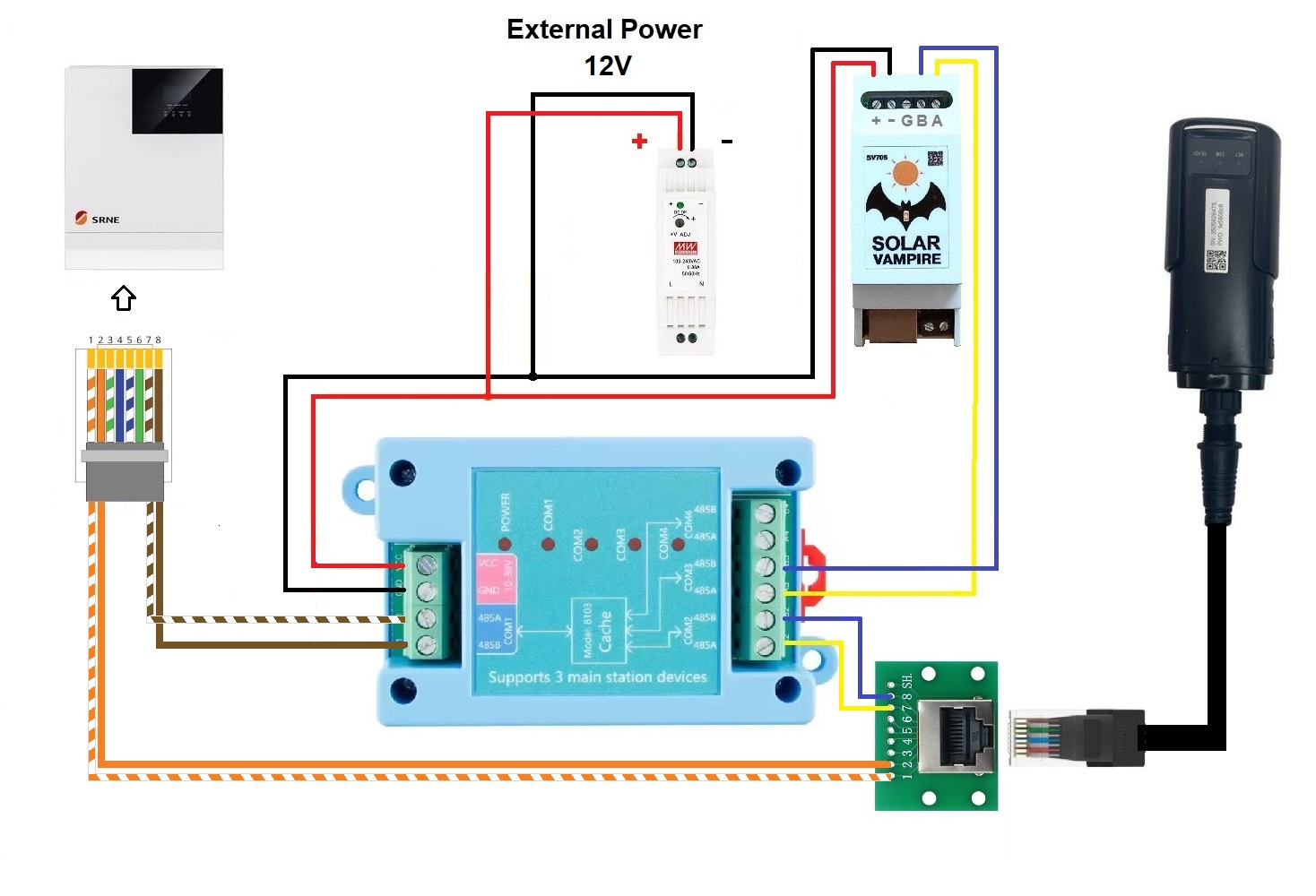
For inverters with an RS485 port, the circuit is simpler. The connection diagram for SRNE inverters is shown below as an example.
In addition to wifi data loggers, you can also combine workSV705and other statistics collection devices. Below is an example of a joint connection diagramSV705and Solar Assistance.
Setting up the YR-8103 router (more details)
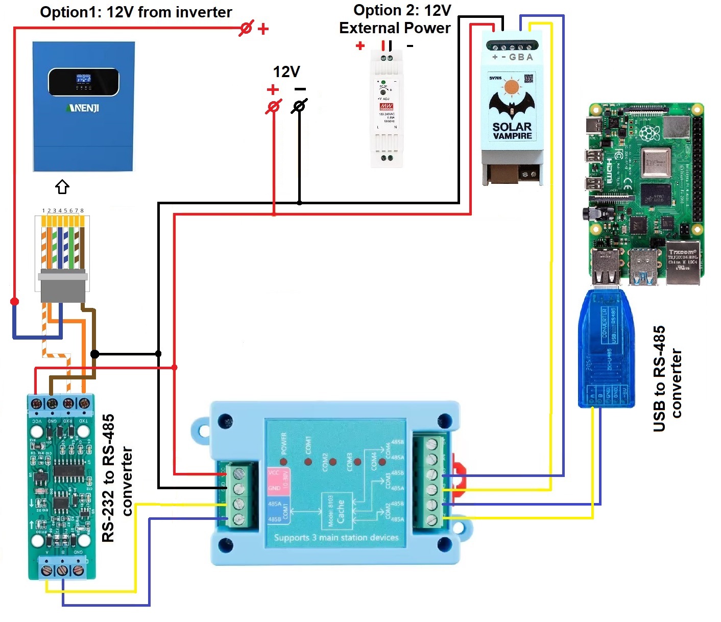
The YR-8103 does not have auto speed adjustment. From the factory, all device ports are set to 9600 speed. This speed is suitable for Anenji and SRNE inverters. Must inverters require a speed of 19200. Most other inverters have a speed of 2400. Configuring the router is quite simple. You need to connect the router to the PC viaUSB-RS485 converter. We connect the corresponding RS485A RS485B wires on the COM1 port of the YR-8103 router and on the converter. For PC you need to download the configuration program. In thisarchiveThere are instructions and programs with Chinese and English interfaces. We launch the program on the PC. Select the COM port number that corresponds to the USB-RS485 converter. Then we supply power to the YR-8103. Now you need to press the CONN button within 5 seconds. The program will contact the device and show its configuration on the screen.
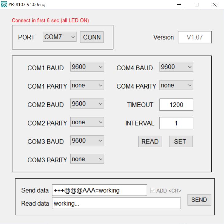
After this, you need to change the speed on all ports to the desired one. Also, if necessary, you can change the Timeout and Port Polling Interval in ms. After changes, you must press the SET button. After this, you can turn off the power and assemble the working circuit.
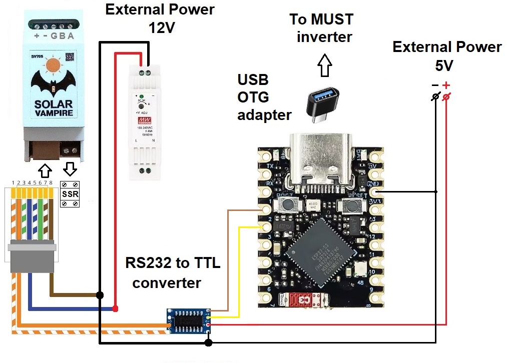
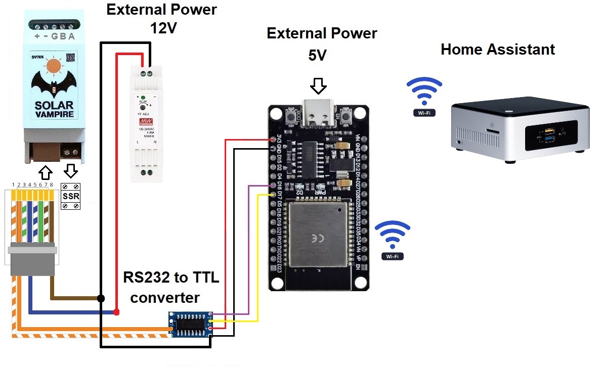
The third method allows you to connectSV705simultaneously with Home Assistant. It is as follows. We connect the inverter to Home Assistant using known methods. We configure it to export inverter data. Let's assemble a simple inverter emulator circuit on ESP32 and connect it to SV705. The emulator will receive real-time data from the real inverter and work with the SV705. This option is described in more detailHere.
Additional schemes
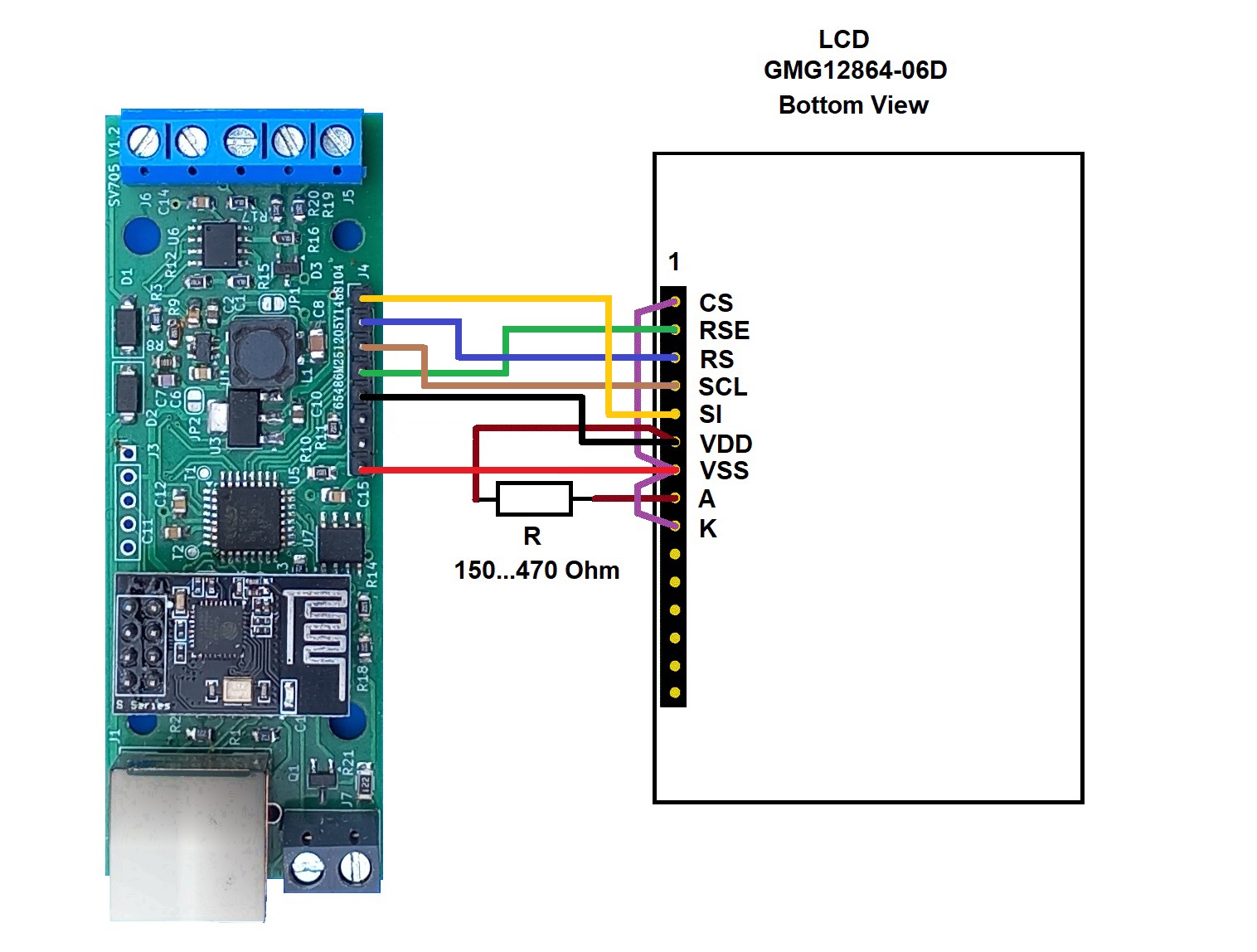
Connection diagram for SV705 to LCD
The SV705 device can display its operational information on the LCD screen. If you wish, you can connect a similar LCD to your device. The connection diagram is below. Unfortunately, we cannot yet offer a ready-made device case for this option. You will have to make it yourself.
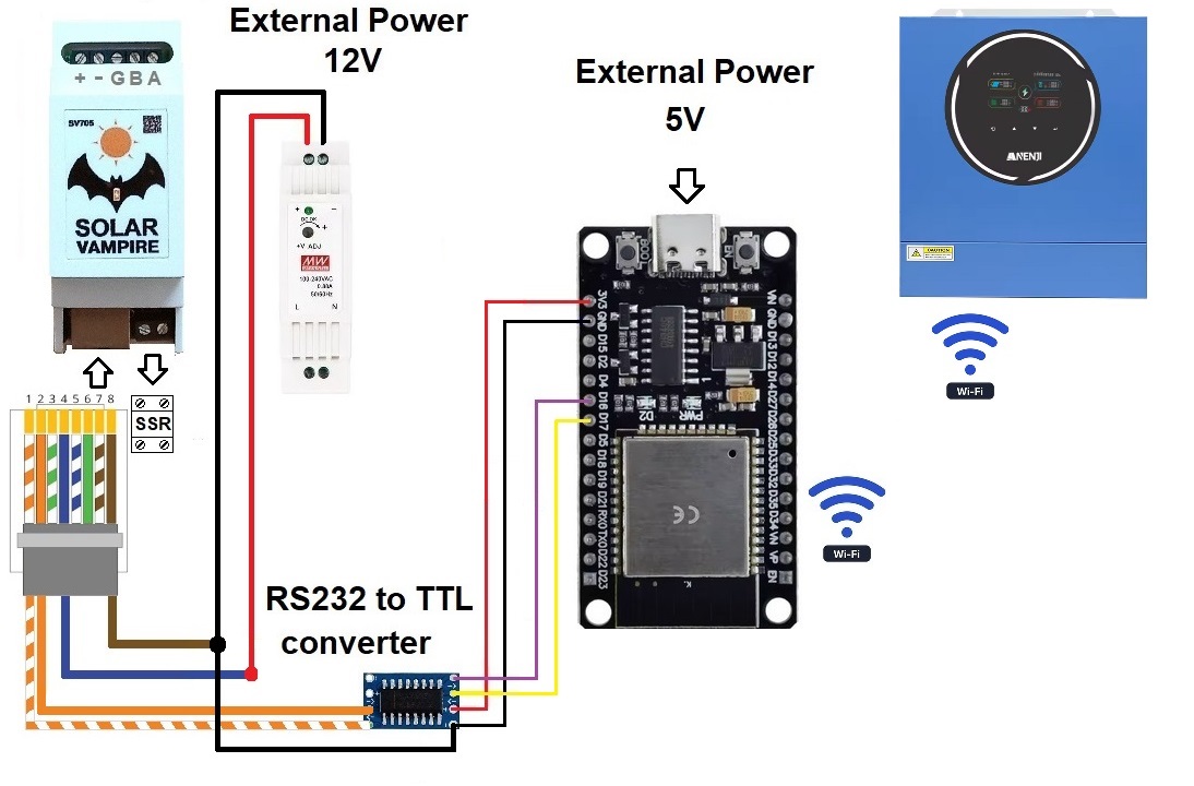
Connection diagram to Anenji/Aninerel inverters with built-in wifi datalogger
Some models of these inverters come with a built-in wifi data logger. This makes connecting external devices difficult. A simple circuit on ESP32 is a wifi<->RS232 bridge. It allows you to connect SV705 to such inverters via “external” RS232. This is described in more detailHere
Connection diagram for inverters with USB Type B connector
Some inverters have a USB Type B connector for connection. For example, some Must inverter models have only such a connector. Inside, a CH340 chip is connected to this connector, which converts USB to UART. This makes connecting external devices difficult. A simple circuit on the ESP32S3 is an RS232<->USB bridge. It allows you to connect SV705 to such inverters through such a bridge. This is described in more detailHere