- Control via WiFi, not Bluetooth;
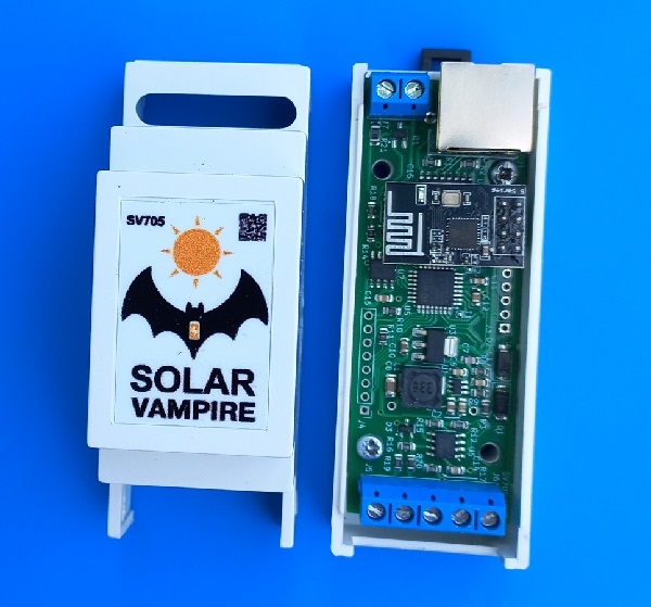
- Ports RS232, RS485 instead of one RS232;
- Switching power supply (reduced own consumption of the device);
Device operation
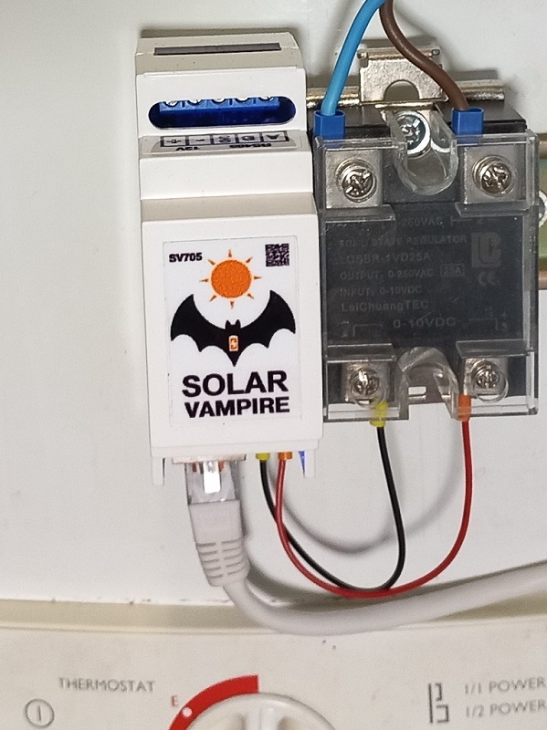
Possible connection diagrams for the SV705 device are shown in this page. Connect your device SV705 according to the circuit recommended for your inverter. First you need to make sure that the device is receiving power. This will be visible from the indicator LEDs located on the RJ45 connector. The left LED indicates the transmission of a data request, the right LED indicates the inverter response. These LEDs are different colors; specific colors may vary depending on connector design. Data exchange occurs once per second. If both LEDs do not blink, the device is not receiving power via the cable from the inverter or from an external power supply for some circuits. It is necessary to check the correct installation. If only the left LED is flashing, the device is not receiving a response from the inverter. The reason may again be incorrect cable wiring or a mismatch in the exchange protocol. The exchange protocol can be changed later on the settings page.
To control your SV705, you must first connect it to your home WiFi network. To do this, you need to supply power to the device. After some time, the device will “raise” the WiFi access point SV_Config, which has a password of 12345678. You need to temporarily connect to this access point using a smartphone and enter 192.168.4.1/config in the address bar in any browser. After this we will be taken to the settings page SV705
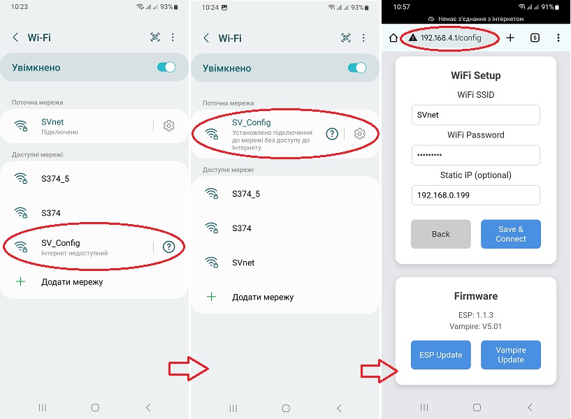
Now you need to fill in the fields in the WiFi Setup section. There you need to enter the details of your home WiFi network. The Static IP field must be adjusted to the parameters of your router. For example, if the router has an address of 192.168.0.1, then for SV705 we enter an address of the form 192.168.0.xxx, if 192.168.1.1, then we enter an address of the form 192.168.1.xxx. Also leave this field empty, in which case the address will be assigned by the router’s DHCP server. After filling in the fields, you must click the Save & Connect button. After that SV705 connect to your home WiFi network. Now the SV705 device will be available on this network at the address that we specified in the settings. For example, at 192.168.0.199. This address can be opened in any browser on a smartphone or computer if they are located on this local network. On this video shows an example of setting up an SV705 connection to WiFi using a smartphone.
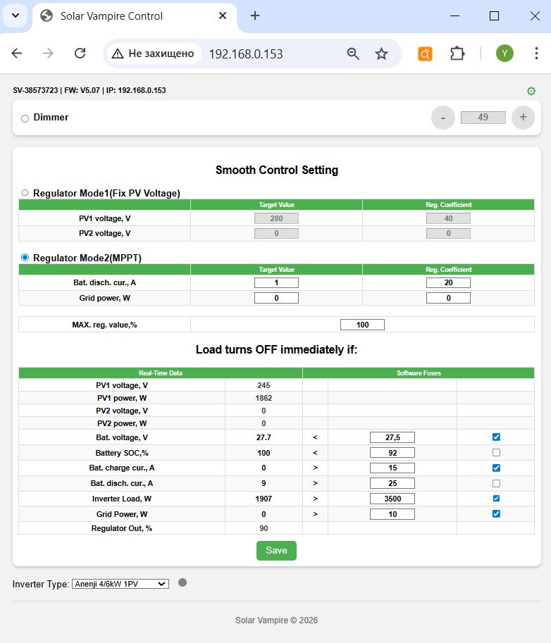
Let's consider the purpose of the adjustment and display organs. At the very top of the page on the left, the device serial number, firmware version and IP address are displayed. In the upper right corner there is a link to the configuration page in the form of a green gear. We have already become acquainted with this page above, when the device was operating in access point mode. This page is also available in always connected WiFi mode. Below are the main controls of the device. Externally, the interface was consistent with the previous version of the SV701 device, which worked via Bluetooth. The main differences are: now the device has three operating modes. And the entry of any parameter (one or several at once) must be confirmed by clicking the Save button at the bottom of the page. After configuration, all parameters are stored in the device’s memory and it will continue to work according to them even after the power is turned off and on.
At the top left there is a mode switch betweenDimmer,Regulator Mode1иRegulator Mode2.
Dimmer. This mode allows you to set a fixed load level using buttons on the screen or by directly entering a value. Please note that the 0-100% scale readings refer to the control signal that the device supplies to the solid-state relay. The transfer characteristic of the relay itself is highly nonlinear and depends on the type of relay and even on the instance. Therefore, if you want, for example, to obtain a load power of 50% of its nominal value, then this should be monitored by the readings of external devices or by the readings of the inverter, since this power for a specific relay can be achieved with a control signal value of both 40% and 60%.
Regulator Mode1(Fix Voltage). This is an automatic regulation mode based on a fixed voltage of the solar input. It is similar to the operating mode of our previous device SV701. In this mode, you can set the voltages for two solar inputs, as well as the regulation coefficient for each input. If the inverter has only one PV input, then the settings for the second one are ignored. If the inverter has two PV inputs, but one of them is not used, zero parameters must be entered for this input. The first setting is Target PV voltage, this is the voltage at the solar input of the inverter, which the regulator will try to maintain by increasing or decreasing the load on it. The next setting is the regulator coefficient. The controller itself is algorithmically a type of nonlinear PID controller. The fact is that classic PID controllers are designed to control linear stationary systems. In our case, the system is both nonlinear and nonstationary, because The step of changing the voltage of the target value depends on the degree of illumination of the panels. Therefore, the device regulates according to a nonlinear algorithm developed by us, the details of which are our know-how.
Regulator Mode2(MPPT). This is our new operating mode, which allows you to work not near the inverter's MPPT point like the previous mode, but directly at the current MPPT point! In this mode, you can set target parameters in the form of battery discharge current and network power consumption. As well as regulation coefficients for these parameters. These settings will be discussed in more detail below.
Another common setting for governor modes is the MAX load limiter. Reg. Value. If your load at full power is too powerful for the system, then you can limit it with this setting. And the regulator will not exceed this value during operation.
The next block is for setting up immediate load blocking. This is necessary to take into account the priorities of the inverter's energy distribution, as well as to quickly respond to external influences. On the left is data received in real time from the inverter, and on the right, opposite some parameters, are their threshold values that can be adjusted. In order for a specific parameter to be taken into account in the work, you must also put a tick in front of it.
At the bottom left there is a drop-down list with inverter protocols. Here you need to select your inverter type.
Setting up the SV705
Our global strategy is not to disturb the inverter when it operates near its maximum power point and to add load when it reaches voltage levels above this zone. As mentioned above, an indication that the inverter has left its maximum power point will be an increase in the voltage at the solar input. First, we determine the voltage of the maximum power point according to the panels’ passport data.
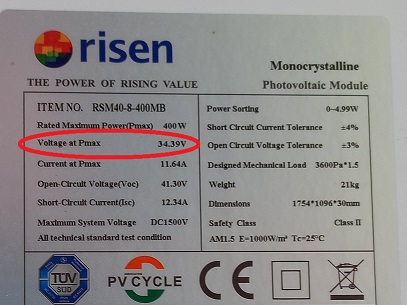
Next, this voltage must be multiplied by the number of panels in the string. This will be the approximate voltage of the maximum string power that the inverter will try to maintain at a panel temperature of 25 degrees. For example, for a string of 4 panels shown above, we get 34.39*4=137.6V. In reality, this voltage can vary depending on temperature and wire resistance. Therefore, two further algorithms for the operation of the SV705 are possible.
Mode No. 1 Operation at fixed voltage PVRegulator Mode1(Fix Voltage)
In this algorithm, the device will carry out smooth adjustment focusing solely on the voltage of the PV inputs. The advantage is simple adjustment. Disadvantage - to achieve maximum efficiency, you must periodically manually change the settings.
The target voltage should be set to 2-10% more than the maximum string power voltage. The greater the difference between the target voltage SV705 and the maximum voltage of the string, the less efficient the utilization of excess energy will be. For the example string of four panels, you can set the value here to 140-145V. However, it should be taken into account that at different times of the year this voltage can change noticeably, so this value should be lowered in summer and increased in winter. To estimate exactly what the current maximum power point voltage is, observe this indicator of your inverter when it is guaranteed to operate at the MPPT point (has a large load or charges the battery with a high current).
The coefficient can take a value from 0 to 100. The higher the coefficient, the faster the adjustment, but the so-called. overshoot. Therefore, we select the value moving from small to large values, observe the operation of the system and find compromise values between the speed of adjustment and its accuracy. For inverters with two PV inputs, the above settings must be made for each input separately. If one of the inputs is not used, then all values for it must be set to zero.
Mode No. 2 Automatic search for the maximum power point
In this algorithm, the SV705 will attempt to automatically track the MPPT point following the inverter. This is achieved as follows. The device gradually increases the load of the inverter until it no longer has enough solar energy. In this case, the inverter will begin to add energy from the battery and/or from the network. The device will see this from the inverter readings and reduce the load. The advantage of this mode is maximum efficiency. The disadvantage is “spot consumption” of the battery or network. Separately, we should dwell on the very facts of “spot consumption” of these energy sources. In the case of a battery, small short-term discharges with a small current do not cause any harm and are immediately compensated by recharging with solar energy. If the network is “eaten up”, there will be no such compensation. Therefore, do not use the mains mixing mode unless necessary.
Target value of battery discharge current. If the current discharge current is higher than this value, the SV705 will begin to reduce the load. Ideally, this suggests setting 0A. However, many inverters have an error in measuring small currents. Therefore, in practice this value should be selected. Most inverters work well at 1-2A. However, among budget models there are examples with poor metrological characteristics, where this value has to be increased to 5-10A. Those. such inverters may well show a discharge current of up to 10A, and according to BMS readings, the discharge current is less than 1A.
Network power target. If the network consumption exceeds this value, the SV705 will begin to reduce the load. Here, too, it begs to be set to 0W. But some inverters are designed in such a way that, being connected to the network, even with an excess of solar energy, they always consume several Watts from it for their service purposes (synchronization with the network, etc.). Therefore, this minimum consumption should be experimentally determined from the inverter readings and values should be set above it. For some budget inverters, the network power is calculated indirectly through the balance of other powers with a large error, because These inverters do not have a built-in grid input power sensor. In particular, this applies to all inverters that operate using the Voltronic&Clones, PowMr Modbus and JSDSolar protocols. Therefore, this adjustment must be used carefully with these inverters.
It can take values from 0 to 100. The higher the value, the more the device will reduce the load of the SV705 due to the fact that the battery is “spot eaten”. The lower the value, the greater the level of this “eating” will be. The coefficient must be selected in such a way as to minimize power fluctuations at the output of the SV705. A zero value disables adjustment.
It can take values from 0 to 100. The higher the value, the more the device will reduce the load of the SV705 in the event of a “spot consumption” of the network. The lower the value, the greater the level of this “eating” will be. The coefficient must be selected in such a way as to minimize power fluctuations at the output of the SV705. A zero value disables adjustment.
This parameter sets the maximum value at the controller output. Please note that the percentages show the control signal level, not the load level. This is due to the fact that SSR LA and VD relay models from different manufacturers, and even different copies from the same manufacturer, may have different adjustment characteristics. Therefore, the range of the regulator covers the spread of ranges of different types of relays. Changing this parameter from 100% makes sense in two cases. The first is if you need to limit the load, making it lower than the maximum load of the boiler. For example, a boiler has a power of 2 kW. And we don’t want it to be loaded above 1 kW. The second case is to increase the speed of adjustment for some relay instances that open completely “too early”. For example, there are relay instances that provide a full load level even at 60% of the control signal level. In both cases, to determine the required level of limitation, it is necessary to turn on the device in the Smart Dimmer mode and, by manually changing the level of the control signal based on the inverter readings, determine the value at which the desired power level will be achieved. For the first case, we look at when the inverter adds +1 kW to its output load. For the second case, we look at when the increase in load on the inverter becomes equal to the full power of the boiler. After that, remember this level and enter it in the MAX reg window. value.
Now let's move on to setting the limiter parameters. When the checkbox next to the parameter is checked, the device SV705 will instantly disconnect the load if the condition between the specified parameter and the corresponding inverter parameter is met, which will be displayed in real time on the left side of the table. If the limiter condition is met, the corresponding parameter will be shown in red. Using these limiters allows you to prioritize solar energy use. They allow you to block the SV705 if there is a higher priority consumer. For example, for the second mode (MPPT), you must use one of the battery limiters (Battery Voltage, SOC, Charging Current) so that the SV705 device does not interfere with battery charging. The first adjustment mode can operate without limiters.
Inverters measure battery voltage quite accurately. Indirectly, the level of this voltage indicates the battery charge level. If we do not want power take-off when the battery is charged below a certain level, we can turn on this limiter and adjust the level. Keep in mind that LiFePo4 batteries have a fairly flat characteristic in the middle of their operating range.
This parameter shows the battery charge level. It is reasonable to set it somewhere around 90-97%. At the end of charging, the batteries are charged with a low current and at this moment the system may already have excess solar energy. But this parameter, unfortunately, for budget inverters can be very inaccurate if the inverter is involved in its calculation. It seems that Chinese inverters calculate it by battery voltage, based on the characteristics of the acid battery. In this case, the limiter does not need to be turned on. If the inverter receives this parameter from the battery BMS via the data cable, then this limiter can be used during operation.
These parameters show the charging and discharging current of the battery. With their help you can limit the operation of the SV705. Keep in mind that some budget inverters measure this parameter with a large error. Therefore, when setting the desired level of limitation, it makes sense to first compare the readings of the inverter and an external meter (DC clamp, BMS readings).
This parameter shows the active AC load of the inverter in Watts. If you do not want it to load above a certain limit, then you can set this limit in the settings. It is reasonable to set a limit of approximately 0.7-0.8 of the maximum power of the inverter to protect it from overload. After reaching this value the load SV705 will be disabled immediately. For example, a refrigerator, air conditioner and microwave oven turned on simultaneously and the total load of the inverter became close to maximum. SV705 will immediately turn off the boiler at this moment and turn it on again when the total load of the inverter decreases.
This parameter shows the inverter's grid consumption. It is designed to limit consumption when the inverter is operating in “mix” mode. Unfortunately, not all inverters have such a hardware meter. For some budget inverters, this power is calculated indirectly through the balance of other powers with a large error. In particular, this applies to all inverters that operate using the Voltronic&Clones, PowMr Modbus and JSDSolar protocols. Therefore, this limiter must be used carefully.
The status of the control output is indicated here SV705 . Using these values, you can dynamically observe how the device controls the load.
After setting all the parameters, you must click the "Save" button. The device will remember them in its memory and will work according to them even after turning the power off and on.
Additional features
The SV705 device can be easily integrated into smart home systems. On the local network, JSON with real-time data is available at the device address .../status (for example http://192.168.0.163/status)
Example JSON device response
{
  "pv1_voltage":132,
  "pv1_power":778,
  "pv2_voltage":0,
  "pv2_power":0,
  "battery_voltage":27.0,
  "battery_soc":90,
  "ibat_charge":23,
  "ibat_discharge":0,
  "load_power":70,
  "grid_power":0,
  "regulator_out":0
}
For example, this is what the setting for Home Assistant will look like
Home Assistant configuration (multiscrape)
multiscrape:
  - name: "Anenji Regulator"
    resource: http://192.168.0.163/status
    scan_interval: 6
    sensor:

      - unique_id: pv1
        name: PV1
        value_template: "{{ value_json.pv1_voltage }}"
        unit_of_measurement: "V"

      - unique_id: pw1
        name: PW1
        value_template: "{{ value_json.pv1_power }}"
        unit_of_measurement: "W"

      - unique_id: load
        name: LOAD
        value_template: "{{ value_json.load_power }}"
        unit_of_measurement: "W"

      - unique_id: out
        name: OUT
        value_template: "{{ value_json.regulator_out }}"
        unit_of_measurement: "%"
Of particular interest is the "regulator_out" field. It shows the amount of load the SV705 is requesting to recover excess solar energy. This means that the SV705 can not only control loads using SSR relays over the wire, but also remote “smart loads” over the local network. We are currently conducting research with one of the possible types of such a load - a miner based on a budget server, and later we will show the results of such integration.
Disclaimer
We warrant that our equipment will perform as described on this website when properly installed and used.
However, responsibility for correct assembly, connection and use rests entirely with the user. We are not responsible for equipment damage, system malfunction, loss of data, or other damage caused by failure to comply with instructions, use of the device in unsuitable conditions, or tampering with the design.
Use of our kits is at your own risk. Before you begin, make sure you understand all aspects of the system assembly and subsequent operation. In case of doubt or lack of experience, we recommend seeking professional help.