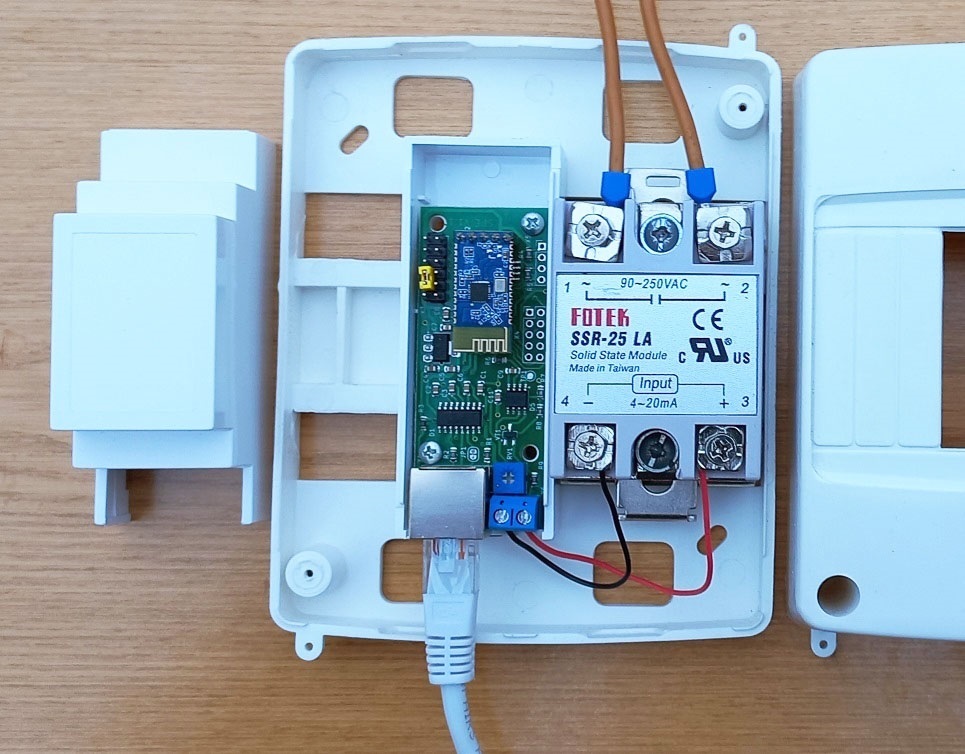
Device operation
Possible device connection diagrams are shown in this page. First you need to connect SV701 to the inverter without connecting the load to the solid state relay and make sure that the device is receiving power. This will be visible from the indicator LEDs located on the RJ45 connector. The left LED indicates the transmission of a data request, the right LED indicates the inverter response. These LEDs are different colors; specific colors may vary depending on connector design. Data exchange occurs once per second. If both LEDs do not blink, then the device is not receiving power via the cable from the inverter. It is necessary to check the wiring of this cable. If only the left LED is flashing, the device is not receiving a response from the inverter. The reason may again be incorrect cable wiring or a mismatch in the exchange protocol. The exchange protocol can be changed later in the BtControl702 application.
Control via Android application
The latest version of the BtControl702 application for Android can be downloaded from downloads page. First you need to establish a Bluetooth connection with the device using the standard means of the Android operating system. Search for devices. Our SV701 will be visible as SV-XXXXXXXX, where the last characters show the serial number of the device. If you purchased the Bluetooth card yourself, then when you turn it on for the first time it will be visible as JDY-31-SPP. You need to pair with this device. The connection password is 1234. When pairing, the Android system may request permission to determine the location. Don't let this bother you. This is a standard requirement of the Android operating system due to the fact that scanning and pairing of Bluetooth devices can potentially be used to determine the user's location. Google allows Bluetooth Low Energy (LE) devices to be scanned and paired only if you have permission to access location data. Please note that your app does not use or collect your location data. The permission request comes solely from the Android system and is intended to ensure the security and privacy of users.
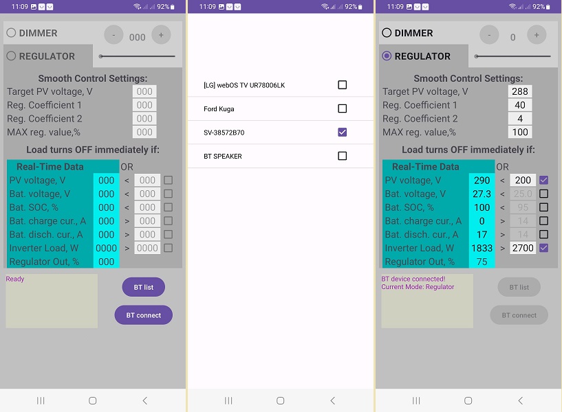
First of all, press the BT List button and get into the window for selecting Bluetooth devices. We put a checkmark next to our device and return to the main window using the system button of the smartphone. This action must be performed once. Upon subsequent launches, the application will already know which device it is paired with.
Now press the BT Connect button and the smartphone will establish a connection with the device SV701.
Let's consider the purpose of the adjustment and display organs. At the top left is the mode switch between Smart Dimmer and Smart Regulator. The first mode allows you to set a fixed load level using a slider or buttons on the smartphone screen. After configuration, all parameters are stored in the device’s memory and it will continue to work in it after the smartphone is turned off and after the power is turned off and on. Please note that the 0-100% scale readings refer to the control signal that the device supplies to the solid-state relay. The transfer characteristic of the relay itself is highly nonlinear and depends on the type of relay and even on the instance. Therefore, if you want, for example, to obtain a load power of 50% of its nominal value, then this should be monitored by the readings of external devices or by the readings of the inverter, since this power for a specific relay can be achieved with the slider position of both 40% and 60%.
The next mode is the main Smart Regulator mode. At the top of the screen there are 4 main settings for the two PV inputs of the inverter. If the inverter has only one PV input, then the settings for the second one are ignored. The first is Target PV voltage, this is the voltage at the solar input of the inverter, which the regulator will try to maintain by increasing or decreasing the load on it. The next two settings are the controller coefficients. The controller itself is algorithmically a type of nonlinear PID controller. The fact is that classic PID controllers are designed to control linear stationary systems. In our case, the system is both nonlinear and nonstationary, because The step of changing the voltage of the target value depends on the degree of illumination of the panels. For example, in our test system in cloudy weather, changing the voltage (around the MPPT point) at the solar input by 10V requires adding/decreasing only 40-50W of load. And at lunchtime on a sunny day in the same system, this already requires ± 800-1000 W. Therefore, the device regulates according to a nonlinear algorithm developed by us, the details of which are our know-how. Two coefficients K1 and K2 are available for adjustment. Another basic setting is the maximum load limiter. If your load at full power is too powerful for the system, then you can limit it with this setting. And the regulator will not exceed this value during operation.
The following seven parameters are for configuring immediate load blocking. This is necessary to take into account the priorities of the inverter's energy distribution, as well as to quickly respond to external influences. On the left is the data received in real time from the inverter, and on the opposite right are their threshold values, which can be adjusted. In order for a specific parameter to be taken into account in the work, you must also put a tick in front of it.
Setting up the SV701
Let's look at the general tuning strategy SV701. First, we should dwell on the metrological characteristics of budget solar inverters made in China. Unfortunately, they are not very good. This is evidenced by both reviews on thematic forums and our own measurements. The discrepancies between the readings of external measuring instruments and the readings of the inverters can be large. Fortunately, inverters measure the solar input voltage quite accurately, and the battery voltage is also measured quite accurately. However, the situation with current measurement is much worse. The inverter can easily show a battery discharge current of 15A, although the battery meter and BMS show zero consumption. The picture is similar with measuring current at the solar input. The inverter may well indicate zero current and zero power at the solar input, although a current of 0.5A flows there, which at a voltage of 300V means 150W of solar energy is supplied. What is noteworthy is that with these inaccurate measurements, the inverter, like a complex closed system, works quite normally - it redistributes energy flows where needed. The problems concern only the readings on the inverter display and those sent via communication interfaces. Why this happens is not very clear. Establishing accurate measurements of these quantities is not a very difficult technical task. Perhaps there is marketing involved here - cheap inverters should not be too good so that users buy expensive inverters :)
Now let's get back to the strategy itself. Our strategy is not to disturb the inverter when it is operating near its maximum power point and to add load when it is operating above this zone. As mentioned above, an indication that the inverter has left its maximum power point will be an increase in the voltage at the solar input. Therefore, our first step will be to determine this maximum voltage power point for our system. It is determined quite simply. Look at the maximum power point voltage indicated for your panels.
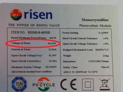
Next, this voltage must be multiplied by the number of panels in the string. This will be the approximate voltage of the maximum string power that the inverter will try to support. For example, for a string of 4 panels shown above, we get 34.39*4=137.6V. In reality, this voltage may vary slightly depending on the temperature and resistance of the wires, but this is not important at this stage of setup. During operation, this shift can be taken into account later.
The target voltage should be set 2-10% more than the maximum string power voltage. The greater the difference between the target voltage SV701 and the maximum voltage of the string, the less efficient the utilization of excess energy will be. However, it is also undesirable to greatly approximate these values, since the device SV701 may begin to compete with the inverter to find the maximum power point. For the example string of four panels, you can set the value here to 140-145V.
Next, let's move on to the coefficients. For most systems, these coefficients can not be changed, leaving the default values. Setting the coefficients for a classic PID controller is a kind of magic :), and even more so for a nonlinear one. We tried to simplify this task for users by selecting and fixing some of the coefficients in our algorithm. The remaining two coefficients are available for adjustment. In automatic control theory, the difference between the target value and the current value is called the control error. They can be considered as follows: K1 has a greater effect when the control error is large, K2 - when the error is small. Each coefficient can take a value from 1 to 100. The higher the coefficient, the faster the adjustment, but the so-called. overshoot. Therefore, we select coefficients moving from small to large values, observe the operation of the system and find compromise values between the speed of adjustment and its accuracy.
For inverters with two PV inputs, the above settings must be made for each input separately. If one of the inputs is not used, then all three values for it must be set to zero.
This parameter sets the maximum value at the controller output. Please note that the percentages show the control signal level, not the load level. As mentioned above, this is due to the fact that SSR LA relay models from different manufacturers and even different copies from the same manufacturer have different adjustment characteristics. Therefore, the range of the regulator covers the spread of ranges of different types of relays. Changing this parameter from 100% makes sense in two cases. The first is if you need to limit the load, making it lower than the maximum load of the boiler. For example, a boiler has a power of 2 kW. And we don’t want it to be loaded above 1 kW. The second case is to increase the speed of adjustment for some relay instances that open completely “too early”. For example, there are relay instances that provide a full load level even at 60% of the control signal level. In both cases, to determine the required level of limitation, it is necessary to turn on the device in the Smart Dimmer mode and, by manually changing the level of the control signal based on the inverter readings, determine the value at which the desired power level will be achieved. For the first case, we look at when the inverter adds +1 kW to its output load. For the second case, we look at when the increase in load on the inverter becomes equal to the full power of the boiler. After that, remember this level and enter it in the MAX reg window. value.
Now let's move on to setting the limiter parameters. All of them are optional, but desirable. When the checkbox next to the parameter is checked, the device SV701 will instantly disconnect the load when the condition between the specified parameter and the corresponding inverter parameter is met, which will be displayed in real time on the green field of the application. If the limiter condition is met, the corresponding parameter will be shown in red.
As a threshold voltage for disconnecting the load, it is reasonable to set a voltage 5-30% below the maximum power voltage of the string. Then the sudden addition of a powerful consumer to the inverter output will cause a sharp voltage drop at the solar input and SV701 will immediately turn off its ballast load. For our example of a four-panel string, it would be reasonable to set this value at 100-120V. If an inverter with two PV inputs has one of the inputs not used, then uncheck the box next to this parameter.
We get the battery voltage from the inverter quite accurately. Indirectly, the level of this voltage indicates the battery charge level. If we do not want power take-off when the battery is charged below a certain level, we can turn on this limiter and adjust the level. Keep in mind that LiFePo4 batteries have a fairly flat characteristic in the middle of their operating range.
This parameter shows the battery charge level. It is reasonable to set it somewhere around 90-97%. At the end of charging, the batteries are charged with a low current and at this moment the system may already have excess solar energy. But this parameter, unfortunately, can also be very inaccurate if the inverter is involved in its calculation. It seems that Chinese inverters calculate it by battery voltage, based on the characteristics of the acid battery. In this case, the limiter does not need to be turned on. If this parameter informs the BMS of the battery via the data cable, then the situation will be better and this limiter can be used during operation.
This parameter shows the active AC load of the inverter in Watts. If you do not want it to load above a certain limit, then you can set this limit in the settings. It is reasonable to set a limit of approximately 0.7-0.8 of the maximum power of the inverter to protect it from overload. After reaching this value the load SV701 will be disabled immediately. For example, a refrigerator, air conditioner and microwave oven turned on simultaneously and the total load of the inverter became close to maximum. SV701 will immediately turn off the boiler at this moment and turn it on again when the total load of the inverter decreases.
The status of the control output is indicated here SV701. Using these values, you can dynamically observe how the device controls the load.
Once you have configured all the settings, you can exit the application. The device will remember them in its memory and will work according to them. Then you can connect again at any time via Bluetooth, observe the operation of the system, or adjust something.
Examples of setup and operation
This video shows an example of the setup and subsequent operation of a test system consisting of an Anenji 4kW inverter, Risen 400W panels and a 7kWh battery. The panels are included according to the 2x4 pcs scheme. The panels are located on two slopes of the East-West roof, 4 pieces on each slope. A 900W water supply pump and a 1.7kW boiler are connected to the inverter via SV701. After the connection is established, the device is configured from default values for a specific system. After this, the device puts the system into optimal solar energy extraction mode. At a timing of 1:43 the water supply pump is turned on, at 2:25 it is turned off. The system processes these impacts.
Below are the performance graphs of our other test system. This system consists of a Jesudom VM4 Twin 4kW inverter, Risen 400W solar panels 8 pcs in series, and a 7kWh battery. The load of this system is the electrical network of an ordinary residential building. Powerful consumers include a boiler, a water supply pumping station, a microwave oven, and an air conditioner.
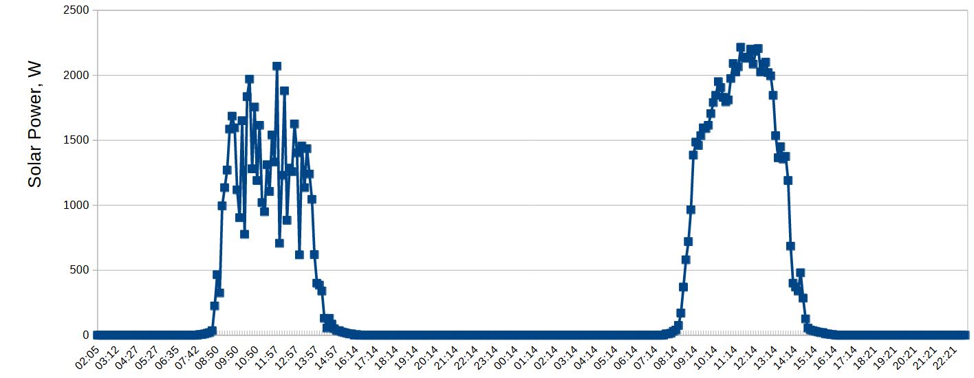
The first graph shows the solar energy utilization of our test system over two consecutive sunny days. Power was measured at the solar input using an external DC wattmeter. On the first day the system worked with the SV701, the next day - with it turned on. The graph shows that without a device, a lot of potentially available energy remains unclaimed.
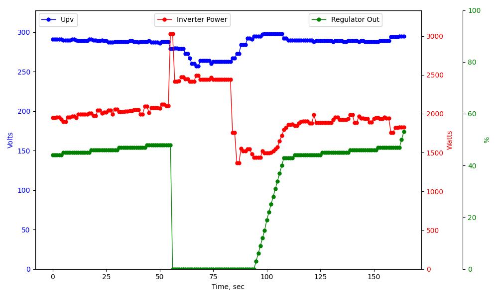
The following graph shows the behavior of this test system over time. During system operation, the system maintained the solar input voltage at about 290V by partially loading the boiler (about 40%), which allowed about 2000W of solar energy to be removed at that time. At the 55th second, the pumping station engine turned on, which sharply increased the system consumption to 3000 W. Device SV701 instantly (2 sec delay) responded to this by completely turning off the boiler, which made it possible to reduce consumption to 2500 W. At the 84th second, the pump turned off and the system smoothly added the boiler load to the previous level of total consumption of about 2000W.
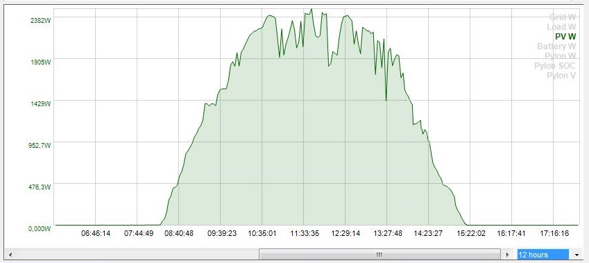
Below is a graph of the solar input power of this test system taken using MultiSIBcontrol software. She worked in her usual mode simultaneously with the device SV701. The graph shows that the system has quite fully collected the energy of a sunny winter day. How to combine the operation of SV701 and the MultiSIBcontrol program is describedHere.
Disclaimer
We warrant that our equipment will perform as described on this website when properly installed and used.
However, responsibility for correct assembly, connection and use rests entirely with the user. We are not responsible for equipment damage, system malfunction, loss of data, or other damage caused by failure to comply with instructions, use of the device in unsuitable conditions, or tampering with the design.
Use of our kits is at your own risk. Before you begin, make sure you understand all aspects of the system assembly and subsequent operation. In case of doubt or lack of experience, we recommend seeking professional help.